Apparatus Schematics


Table of Contents

1. Basic

2. Dual Output

3. Multiple simultaneous delay


1. Basic
-- Single delay version for Doppler velocimetry and 2.5x resolution boosting


Figure A1. Schematic of basic EDI apparatus. Lens images light from source (fiber) to plane of the interferometer mirrors where fringes are formed. This plane is re-imaged by another lens to the entrance slit plane of spectrograph. This way, the interferometer phase can be made to vary linearly along the slit length, which is useful for recording all phases in a single exposure. (Another data taking mode is to have a uniform phase every along the slit and phase step in several exposures by moving the mirror on the PZT.) The interferometer is made to be angle independent by inserting a glass plate in one of the arms, and superimposing the virtual image of the mirror on the plane of the other mirror. For ray paths this creates the appearance of zero delay (for all angles), but because of the slower speed of light in glass this creates a nonzero temporal delay, which creates the needed sinusoidal dependence on wavenumber (which is wavelength).


2. Dual output scheme
-- In a facility instrument both interferometer outputs would be used so that net transmission would be near unity-- only the minor reflectance losses of the additional optics would be present.

Figure A2. Scheme for using a split mirror and a Mach-Zehnder interferometer to direct both complementary outputs to the slit of a spectrograph, on separate but nearby CCD pixels (otherwise no fringes would exist). Similar schemes exists for the case of a Michelson. For ideal optics, every photon that enters the interferometer will reach the spectrograph. The interferometer can be thought of as a sorting device, that sends photons to either of two outputs depending on slight wavelength. The spectrograph provides the rough wavelength organization, and the interferometer, like a vernier dial, provides the fine wavelength discrimination.


3. Multiple simultaneous delay
-- For snapshot recording of transient or time dependent phenomena with resolution boosting 3x - 15x or more.


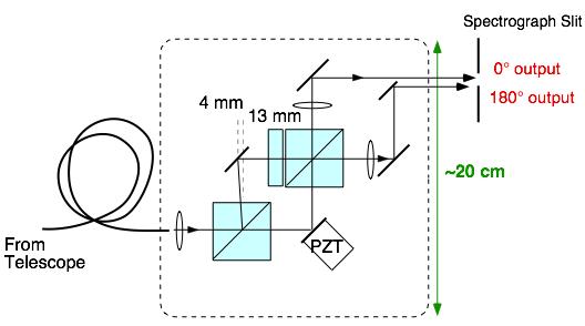
Figure A3. Scheme for measuring multiple delay fringing spectra simultaneously. In this side view the spectrograph dispersion is into the paper (although the colored spectrum is depicted horizontally). Internal details of the interferometer are omitted except for the stepped shape of one of the two mirrors. Because the EDI is an imaging interferometer, different vertical locations along the interferometer mirror are imaged to independent locations along the spectrograph slit and CCD. The interferometer mirror and etalon are divided vertically into steps to produce the different delay values, which are measured simultaneously on the same CCD. The thicknesses of the steps are chosen to keep the virtual image of the steps all in the same plane, to preserving the wide angle ability.

The stepped shape of the mirror should not be confused with a diffraction grating, because the beamlets are imaged to separate positions on the CCD and therefore due not communicate with each other.

With multiple delays, the effective resolution can be boosted by factors much greater than 2.5x. Recently 6x boosting has been demonstrated (
Figures, report Ref. 8, using theory in report Ref. 7) with different delays measured sequentially by a single delay EDI. The Gaussian lineshape resolution that can be obtain will be proportional to the number of delays used (M), with a boost factor approximately as (1+1.5M).

www.SpectralFringe.org site maintained by
David Erskine
erskine1@llnl.gov

Back to EDI home